The Starblast.io ship editor can be found here.
Interface
The ship editor interface consists of an input body of text taking up the left half of the screen, as well as a rendered output of the ship on the right. Any edits made to the input text will cause the output render to immediately update unless the text includes some type of syntactical error, in which case the model shown will be of the last error free script provided. The right hand side consists of a rendered image of the ship itself in the center, which can be clicked and dragged to change the orientation, and silhouette of a top down view of the current hitbox of the ship.. Atop the render body is a series of eight buttons. The first two allow you to save the current body of text to a text file, or load a text file into the editor. The second two buttons allow you to download a png image of the ship in its current orientation, or download a converted .obj file. The fifth and sixth buttons solely effect the cosmetics of the rendered ship, by changing the color of the ship and the material respectively. This is to preview how this ship would look if a user with and Elite Commander Pass was to use that ship with a material other than zinc selected. The next button in the row will allow you to load a file of any ship that is currently in the game into the editor, by clicking on the button, then clicking the desired ship in the tree. The final button above the rendered output is a link to the terms of use of the ship editor, that you must agree to to use.
Ship Script Part 1
Syntax Constants
As is the case with any type of script, syntax is the most important factor to consider when editing. In this case, the number of indentations preceding a line of text is registered by the editor and thus must be of the right length. With this editor, a difference of one space defines a parent from a child.
 bodies:
   main:
     section_segments: 8
     offset:
       x: 0
       y: 50
       z: 10
     position:
The above snippet of text is an example of how lines of text are nested within each other. main: has one more indendation preceding it than bodies: and is one line after, which means that the former is defining something within the latter. section_segments:,offset: and position: are one position further than main: which means they are all defining attributes within main:.
 bodies:
   main:
     offset:
       x: 0
       y: 50
       z: 10
     section_segments: 8
     position:
The above text would act exactly the same as the first. The order of nested attributes can be rearranged freely as long as their child attributes are directly after them.
return model =
The line above is a required bit of syntax and should always take up the first line in the editor. This should be left alone.
Ship Stats:
return model =
 name: 'Condor'
 level: 6
 model: 4
 size: 1.5
 specs:
   shield:
     capacity: [225,400]
     reload: [7,10]
   generator:
     capacity: [70,130]
     reload: [30,48]
   ship:
     mass: 200
     speed: [75,105]
     rotation: [50,70]
     acceleration: [80,120]
The ship statistics will define how the ship will behave in game. As they are a child of the first line they will begin with one indentation. The above code is an example taken from the Condor code. For every instance of two numbers in brackets separated by a comma ([15,20]), it defines a statistic minimum and maximum where an unupgraded ship will have the first number and a fully upgraded ship will have the second number.
name: 'Condor'means that the name of the ship will be Condor. This can be changed to anything as long as it stays within the single quotes.level: 6means that this ship will appear at level 6 in the upgrade tree. This can be changed to any integer.model: 4Unknownsize: 1.5means that the ship size will be multiplied by a factor 1.5 when in game. This can be any positive number.shield:capacity: [225,400]means that the ship has a minimum of 225 shield capacity and a maximum of 400 shield capacity. These can be any integers.reload: [7,10]means that the ship has a minimum of 7 shield regeneration per second and a maximum of 10 shield regeneration per second. These can be any integers.
generator:capacity: [70,130]means that the ship has a minimum of 70 max weapon energy capacity and a maximum of 130 max weapon energy capacity. These can be any integers.reload: [30,48]means that the ship has a minimum of 30 weapon energy regeneration per second and a maximum of 48 weapon energy regeneration per second. These can be any integers.
ship:mass: 200means that the ship will weigh 200 units where the higher number means the ship will weigh more. This can be any integer.speed: [75,105]means that the ship will have a minimum terminal velocity of 75 and a maximum terminal velocity of 105. These can be any integers.rotation: [50,70]means that the ship will have a minimum rotation speed of 50 and a maximum rotation speed of 70. These can be any integers.acceleration: [80,120]means that the ship will have a minimum speed acceleration of 80 and a maximum speed acceleration of 120. These can be any integers.
Additionally if the ship charges rather than firing lasers in the manner of the barracuda, it has another few lines appended to the end as a child of ship:.
     dash:
       rate: 2
       burst_speed: [160,200]
       speed: [120,150]
       acceleration: [70,70]
       initial_energy: [50,75]
       energy: [20,30]
dash:burst_speed: [160,200]means that the ship will have a minimum initial ram speed of 160 and a maximum initial ram speed of 200. These can be any integers.speed: [120,150]means that the ship will have a minimum sustained charge speed of 120 and a maximum sustained charge speed of 150. These can be any integers.acceleration: [70,70]Unknowninitial_energy: [50,75]means that the ship will have a minimum initial ram cost of 50 and a maximum initial ram cost of 75. These can be any integers.energy: [50,75]means that the ship will have a minimum sustained charge cost of 20 per second and a maximum sustained charge cost of 30 per second. These can be any integers
Ship Script Part 2
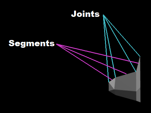
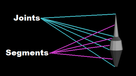
A diagram of a basic object in the editor defining the joints and the segments for wings
A diagram of a basic object in the editor defining the joints and the segments for bodies
After the ship statistics are defined you can move onto the ship model itself. There are two types of structure that all ships are constructed out of, the first of these being bodies and the second being wings. These both act the same with collision detection. Both wings: and bodies: are children of the first line in the editor so they will have one indentation. For any instance of a set of numbers in brackets separated by a comma ([13,25,33]), that is a set of points or segments. There is no limit to the amount of numbers you can put in here separated by commas. The origin is the point in the 3D area at 0,0,0. For the purpose of this tutorial, there will be two parts referred to in each structure. These being the joints and the segments. Joints are essentially the actual measurements, while the segments are the polygons drawn between two joints.
Wings
The wings class of structures solely effect the look of the ship and the hitbox of the ship in the case of a collision. Every instance of wings will be mirrored on both the left and right sides of the model. All joints of a wing or set of wings lies on a Y axis.
 wings:
   back:
     offset:
       x: 0
       y: 25
       z: 10
     length: [90,40]
     width: [70,50,30]
     angle: [-30,40]
     position: [0,20,0]
     texture: [11,63]
     doubleside: true
     bump:
       position: 10
       size: 20

Available textures
wings:back:this can be named anything at all as long as the syntax is maintained.offset:x: 0means that the initial point of the wings is offset by 0 units on the x axis. This can by any number.y: 25means that the initial point of the wings is offset by 25 units on the y axis. This can be any number.z: 10means that the initial point of the wings is offset by 10 units on the z axis. This can be any number.
length: [90,40]means that the length of the first segment of these wings will be 90 units long, and the second will be 40 units long. These can be any numbers.width: [70,50,30]means that the width of the first joint of these wings will be 70 units wide, the second will be 50 units wide and the third will be 30 units wide. These can be any numbers.angle: [-30,40]means that the angle along the y axis of the first segment of these wings will be -30 degrees, and the second will be 40 degrees. These can be any numbers.position: [0,20,0]means that the offset along the y axis of the first joint of these wings will be 0 units, the second will be 70 units and the third will be 0 units. These can be any numbers.texture: [11,63]means that the texture of the first segment of these wings will be texture 11, and the second will be texture 63. These can be any numbers, though only a select few will be unique textures.doubleside: truemeans that both sides of this structure will be rendered. This can be either true or false.bump:position: 10means that the bump will occur on the wings at 10 units along the y axis. This can be any number.size: 20means that the bump will have a height of 20 units which is dependent on the width of each segment. This can be any number.
Bodies
The bodies class of structures are, unlike the wings, capable of firing lasers from the from and a propulsor effect from the back. The latter is purely cosmetic as the thrust and agility was defined in part 1. The body structures will not be mirrored on the left and right sides unless the offset on the x axis is not equal to 0.
 bodies:
   main:
     section_segments: 12
     offset:
       x: 0
       y: -30
       z: 10
     position:
       x: [0,0,0]
       y: [0,10,35]
       z: [0,-3,12]
     width: [5,13,4]
     height: [0,8,4]
     texture: [63,8,2]
     propeller: true
bodies:main:this can be named anything at all as long as the syntax is maintained.section_segments: 12means that along the y axis 12 faces will be drawn to the specifications. This can be any positive number.offset:x: 0means that the initial point of the body is offset by 0 units on the x axis. This can by any number.y: -30means that the initial point of the body is offset by -30 units on the y axis. This can be any number.z: 10means that the initial point of the body is offset by 10 units on the z axis. This can be any number.
position:x: [0,0,0]means that the offset along the x axis of the first joint will be 0 units, the second will be 0 units and the third will be 0 units. These can be any numbers.y: [0,10,35]means that the offset along the y axis of the first joint will be 0 units, the second will be 10 units and the third will be 35 units. These can be any numbers.z: [0,-3,12]means that the offset along the z axis of the first joint will be 0 units, the second will be -3 units and the third will be 12 units. These can be any numbers.
width: [5,13,4]means that the width of the first joint will be 6 (2*3) units wide, the second will be 26 (2*13) units wide and the third will be 8 (2*4) units wide. These can be any positive numbers.height: [0,8,4]means that the height of the first joint will be 0 (2*0) units wide, the second will be 16 (2*8) units wide and the third will be 8 (2*4) units wide. These can be any positive numbers.texture: [63,8,2]means that the texture of the first segment of this body will be texture 63, the second will be texture 8 and the third will be texture 2. These can be any numbers, though only a select few will be unique textures (see above).propeller: truemeans that given the correct conditions, this body will produce a propulsor animation out of the back. This can be either true or false.
For the body to fire a laser a few more lines need to be appended to the end of this.
     laser:
       damage: [30,60]
       rate: 2
       type: 2
       speed: [150,200]
       number: 1
       angle: 0
       error: 0
laser:damage: [30,60]means that this laser will deal a minimum of 30 damage and a maximum of 60 damage. These can be any positive numbers.rate: 2means that this laser will fire twice per second. This can be any positive numbertype: 2Unknownspeed: [150,200]means that this laser's projectiles will travel at a minimum velocity of 150 units and a maximum velocity of 200 units. These can be any positive numbers.number: 1means that each round will fire 1 laser. This can be any positive numberangle: 0means that each laser will fire at a 0 degree angle. This can be any numbererror: 0means that each laser can fire off target by 0 degrees. This can be any positive number.
Designing A Ship
This next section will include a step by step tutorial on how to design a ship from scratch. This will assume that you know the terminology and syntax presented in the above sections. For the purpose of this tutorial we will be making a basic level 4 ship called the Gale.
Creating A Sketch
When designing a ship the best way to start, if you have a design in mind, is to draw a simplistic top down view as you would expect it to appear in game. For the initial sketch feel free to draw curves as we will be converting this later on. I chose to color it to get a rough idea of what the final textures will be. If you'd rather use the editor without the use of a sketch first skip ahead to Creating The Model.

The next step will be to convert it into a sketch that will be possible within the confines of the editor. As stated above, there are two structures that you will have access to in the editor. The bodies will all have joints along different X-Z planes, while the wings will all have joints along different Y axes. This means that when you create the sketch you'll need to make all the joints vertical if they are wings, and horizontal if they are bodies.
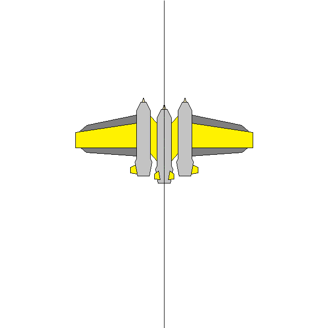
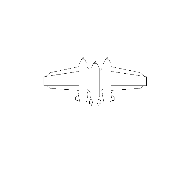
The final step for the sketch is to draw lines where you plan on making different segments in the editor. I chose to make these different colors to the outline as to keep it looking somewhat organized. It is also useful to find the center of all the joints and make a small bisecting indicator. This will come in hand later on when you are converting it to a ship. If you want to ensure that there wont be a gap between a wing and a body, It's helpful to draw a bit of them overlapping as that part wont be seen.
Creating The Model
Now that we have a basic sketch of the design, we are going to need to create the ship piece by piece. Before we do that however, we must initialize the ship code and fill in the ship stats. This ship is going to be about as agile as the crusader, with lesser shields and a bit more energy regeneration, so this is the start I settled on:
return model =
 name: 'Gale'
 level: 4
 model: 4
 size: 1.3
 specs:
   shield:
     capacity: [120,180]
     reload: [5,8]
   generator:
     capacity: [100,120]
     reload: [20,35]
   ship:
     mass: 180
     speed: [75,105]
     rotation: [30,75]
     acceleration: [70,900]
I will be making both bodies first, followed by the 5 sets of wings. I plan on making the ship a bit larger than the crusader in the editor for the sake of screenshots, but the final product will be slightly smaller so rather than a 1.6 size I went with a 1.2. The next step will be to create the main body. The sketch I created luckily was a perfect size to use actual pixel measurements for the editor, but in some cases you'll either need to convert the pixels to another form of measurement, or scale the entire image up/down. I'll be using gimp to get the pixel measurements easily for this. The main body has a series of 10 joint and thus 9 segments. Since the X will be the center, or point of rotation of the ship, I'll need to measure the distance between the tip of the ship and the center to start. This came out to be 76 pixels up which means I will translate the start of the body -76 pixels along the Y axis.

This is where I'll place my first joint with a width of 0 and a height of 0. Next I will measure the distance between the first and second joint, along with the width which came out to be a distance of 12 and a width of 5. This body will be cylindrical so the height will in turn be 5. I'll add a random texture and an offset of 0 pixels on the Y and Z axes to allow this first segment to render.
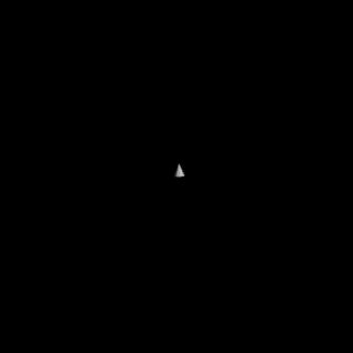
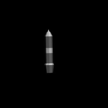
Doesn't look like much yet, but just wait until we add a few more joints. I will repeat the previous step for all of the the joints in the main body measuring the distance from the tip to the next joint. You can leave the texture brackets with just one number to make the entire body/wing one texture, but to make it easier to differentiate between all the segments I chose a pattern of textures 1,3,1,3...
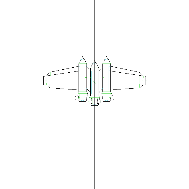
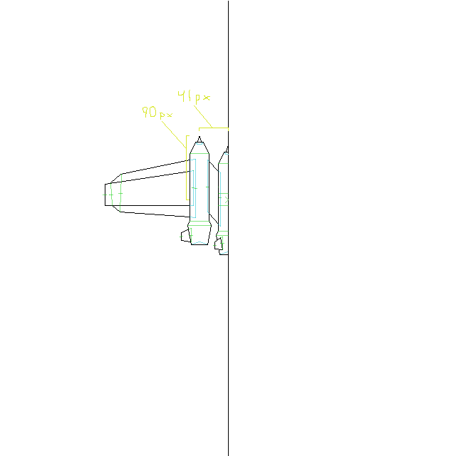
Not a bat start. Next we will be creating the two bodies on either side of the main body. As stated earlier, if the offset on the X axis is not 0 the editor will automatically mirror any bodies on the opposite side. The two side bodies will be identical in dimensions to the main body so I will essentially copy the main body with a new name and translate it to the desired location (this time being 41 px along the X axis and 90 px along the Y axis). Of course we can name bodies and wings anything, though to keep this somewhat organized I decided to name the outer two bodies sides.
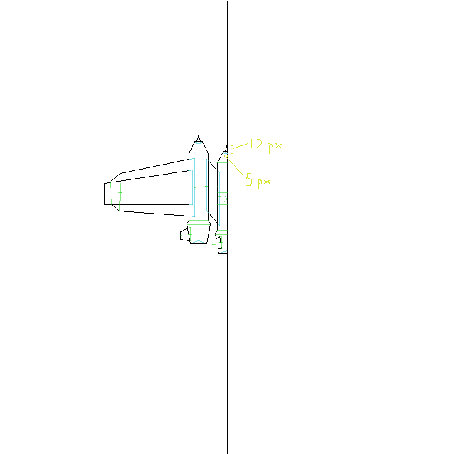
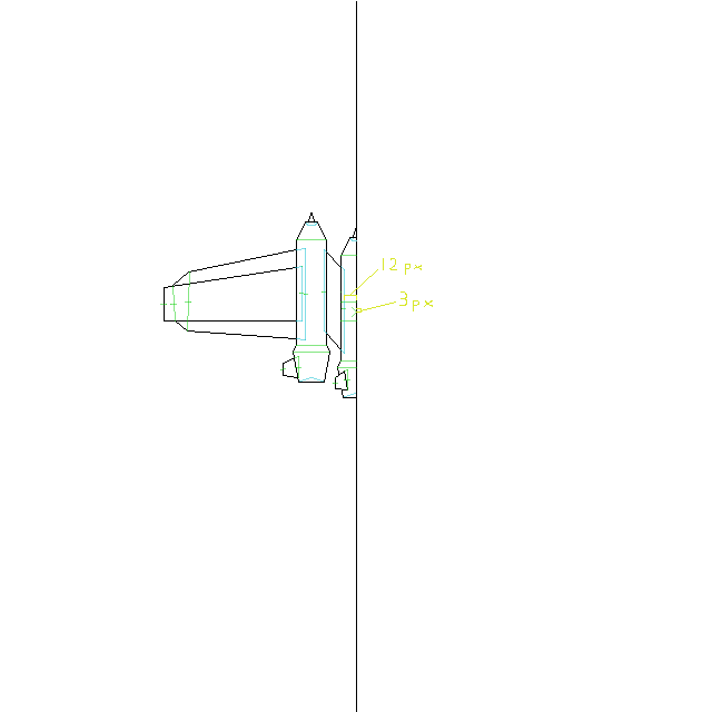
Well, this is starting to take shape. Now that all the bodies are completed, we can move onto the wings. The first will be the wings connecting the two bodies. The first step here will be finding the innermost joint and using the bisector to find the offset on both the X and Y axes, which came out to be 12 px and 3 px respectively. We will then make the first joint width the length of vertical line we drew along the first joint.
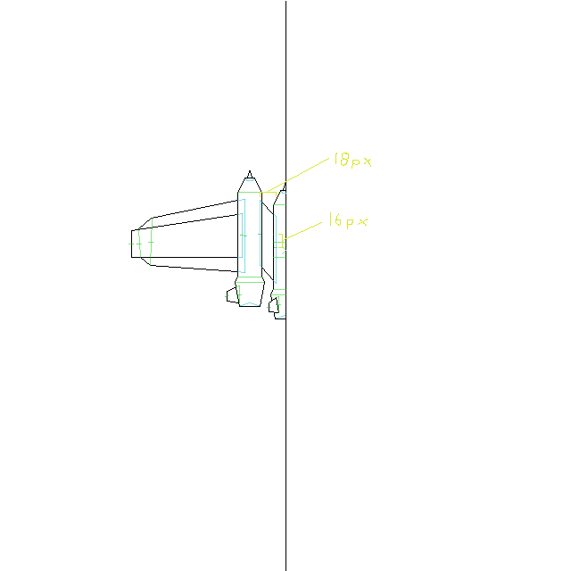
Of course with only one joint nothing new will be rendered, so we'll need to move on to the next joint. To create the next joint for this wing, we will need to find the Y offset from the first wing and set that to position, then find the X offset and set that to the length. This is because the length refers to the length between joints. These measurements came out to be 18 px along the X axis and 16 along the Y axis. Since the shape we drew for this set of wings in a parallelogram, the width can be copied over. The angle of this wing segment will be set to 0 and the bump will have a size of 0. We can also leave doubleside at false since you will never see the underside of this wing.
Now this is starting to look a bit more like a ship. Next we will be creating the outer two wings in the same fashion as the last set which I will skip over.